 English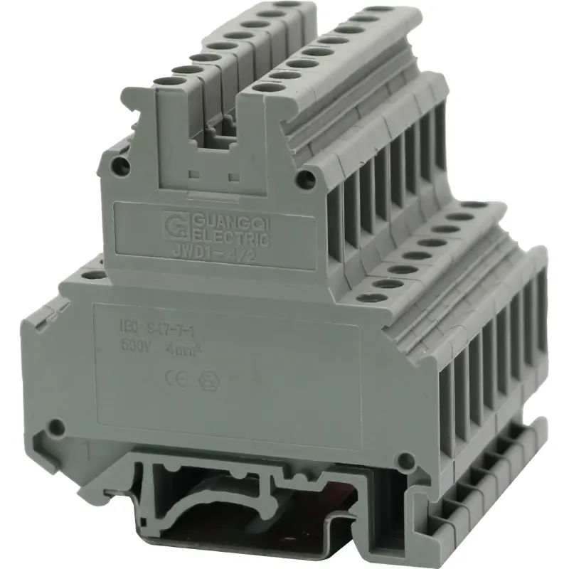
| Terminal thickness: 6.2 | ||||
| Rigid conductor | Flexible conductor | I | Ui | |
| (mm2) | (A) | (V) | ||
| IEC 60947-7-1 | 0.2-4 | 0.2-4 | 24 | 500 |
| Description | Color | Schematic diagram | Type | |
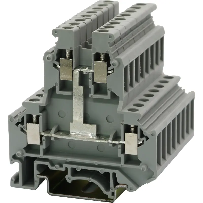
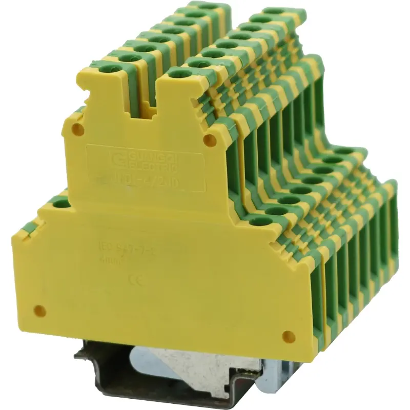
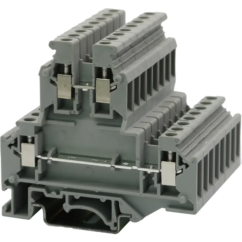
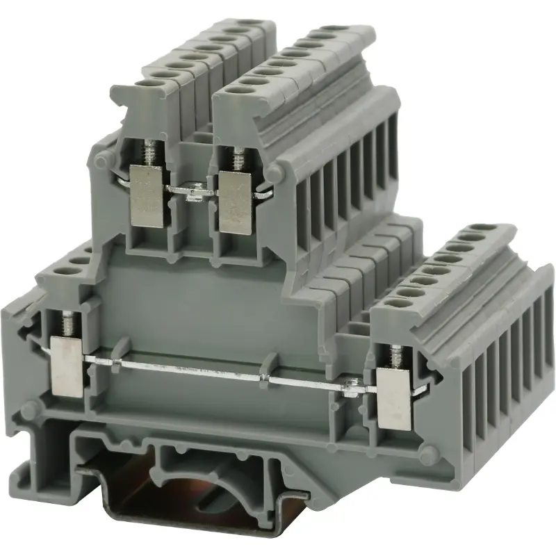
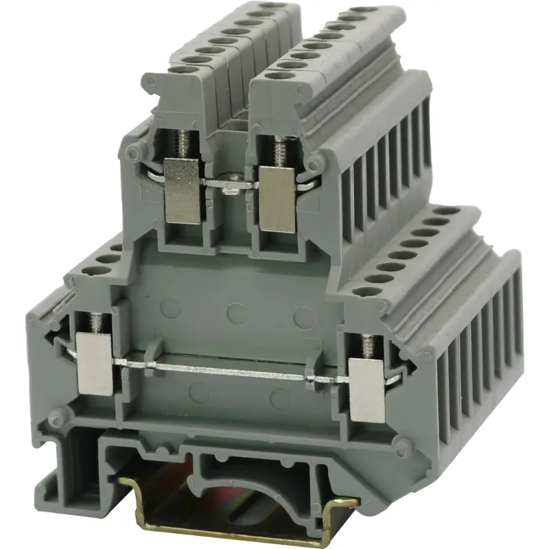
| Terminal: | Grey | JWD1-4/2 | ||
| With general-purpose locating base, suitable for standard mounting rails | ||||
| and | ||||
| Blue | JWD1-4/2 BU | |||
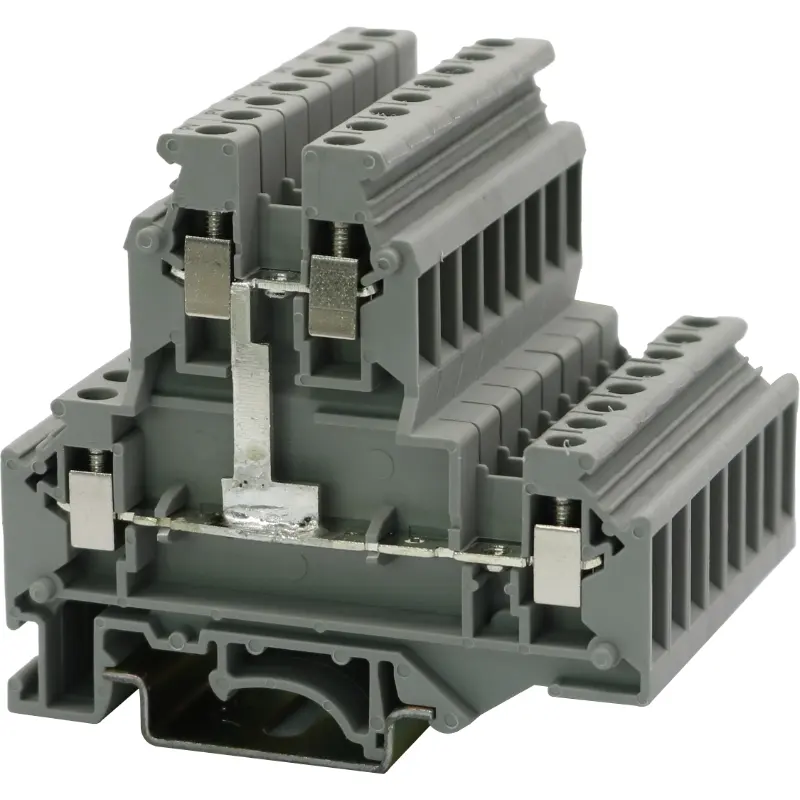
| Top and bottom interconnected terminals: | Grey | |||
| The mounting and use methods are the same as above; the conducting plates in the upper and lower layers are interconnected to achieve the same potential of top and bottom connecting points. | ||||
| Blue | ||||
| (1) End plate: (thickness: 2.5) | Grey | 2.5-4/2 G | ||
| One additional piece must be attached to the end of each terminal strip set. If it is mounted in the center of the terminal strip, the creepage distance may increase. | ||||
| Blue | 2.5-4/2 G BU | |||
| (2) Compensating end plate: (thickness: 2.5) | Grey | 2.5-4/2BD | ||
| It is used to offset interlayer displacement while it is adjacent to an ordinary terminal. | ||||
| Blue | 2.5-4/2BD BU | |||
| (3) Compensating end plate: (thickness: 2.5) | 2.5-4/2 BD-1 | |||
| It is used for terminal locating and fastening of the terminal strip or for offsetting interlayer displacement while it is arranged with other terminals in the same group. | ||||
| (4) Central liaison part: | ZL 6/10 | |||
| It is used to connect terminals with the same specification and form a liaison terminal group; each part has 10 digits (supplied with screws) that can be further divided at will. | ||||
| (5) Connecting sheet: | LJ 6/2 | |||
| For central connection of more than 10 digits | ||||
| (6) Edge liaison part: | 2 digits: | BL 6/2 | ||
| Its role is the same as that of the central liaison part (4); with insulation on the back side; 10 digits that can be further divided at will | ||||
| 3 digits: | BL 6/3 | |||
| 10 digits: | BL 6/10 | |||
| (7) Jumping liaison part: | KL 6/10 | |||
| With the spacer (8), it can connect any non-adjacent terminals in the center to form a jumping liaison terminal group. | ||||
| (8) Spacer: | K6 | |||
| Used as a spacer block between the accessory of the jumping liaison part (7) and the conductive part of the terminal | ||||
| (9) Divider: | GP-1 | |||
| It is used to separate two adjacent liaison terminal groups and can be inserted after assembly, without any effect on the overall space. | ||||
| (10) Group partition: (thickness: 2.5) | 2.5-4/2 GF | |||
| Used for separation of each terminal group; with dual effects (visible grouping and electrical isolation) | ||||
| (11) Tag: | ZP6 | |||
Terminal dimensions | ||
Thickness / width / end plate thickness | [mm] | 6.2/56/2.5 |
Height (TH 35:7.5 / TH 35:15 / G 32:15) | [mm] | 62/69.5/67 |
Technical data based on IEC/DIN VDE standards | ||
Maximum rated working current / cross-sectional area | [A] / [mm2] | 32/4 |
Maximum cross-sectional area of conductors (rigid / flexible) that can be connected if any edge liaison part is used: | [mm2] | 4/2.5 |
Rated impulse withstand voltage / degree of pollution | [kV]/- | 6/3 |
Over-voltage category / insulation material group | -/- | lll/l |
Connection capacity | ||
Flexible conductor with tubular bare terminal / tubular pre-insulated terminal | [mm2] | 0.25-4/0.25-2.5 |
Connection of multiple conductors (two conductors with the same cross-sectional area) | ||
Rigid conductor / flexible conductor | [mm2] | 0.2-1.5/0.2-1.5 |
Flexible conductor with tubular bare terminal | [mm2] | 0.25-1.5 |
Flexible conductor with DEV-tubular pre-insulated terminal | [mm2] | 0.5-1.5 |
Stripping length | [mm] | 8 |
Screw type | M3 | |
Torque | [Nm] | 0.6-0.8 |
Insulation material type | PA | |
Material flammability according to UL94 | V0 | |
Rated working voltage / rated working current / wire gauge | UL:[V]/[A]/AWG | 600/30/26-10 |
Note: When an edge liaison part is used, a cable below 1.5 mm2 should be used for a 2.5 mm2 terminal; corresponding cables should be used for terminals with other cross-sectional areas (mm2). | ||