 English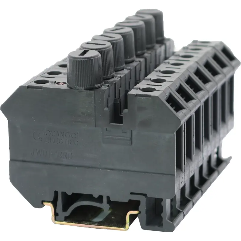
| Terminal thickness: 8.2 | ||||
| Rigid conductor | Flexible conductor | I | Ui | |
| (mm2) | (A) | (V) | ||
| IEC 60 947-7-3 Used as a terminal for breaking capacity | 0.2-4 | 0.2-4 | 6.3* | 800 |
| With fuse | 0.2-4 | 0.2-4 | Note 1) | |
Description | Schematic diagram | Type | Part Number | Package quantity | ||||
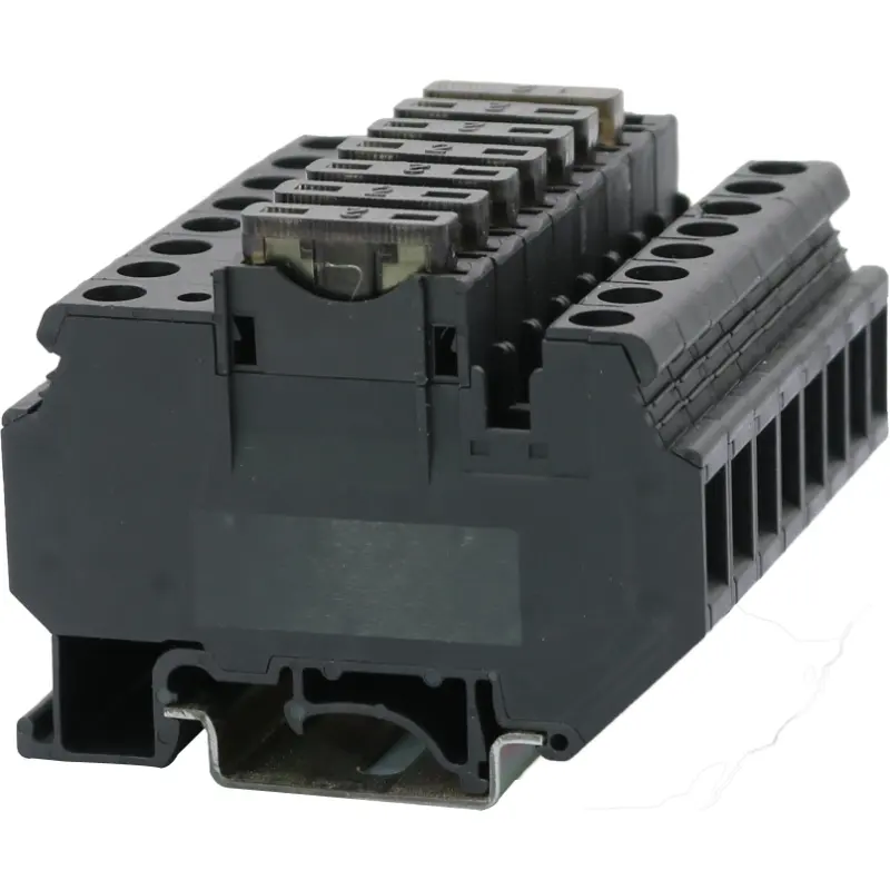
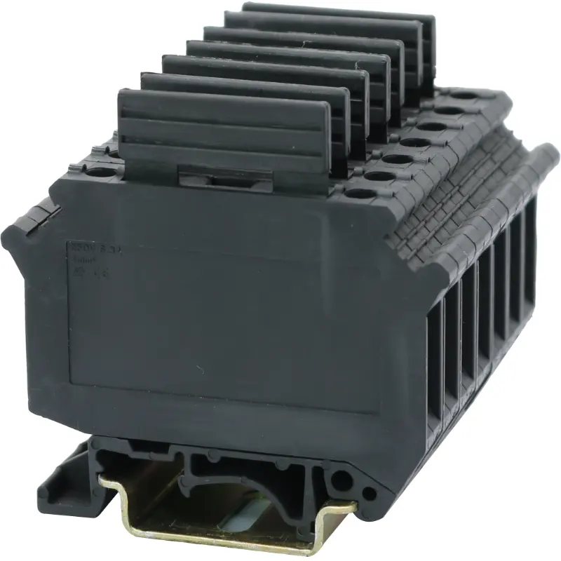
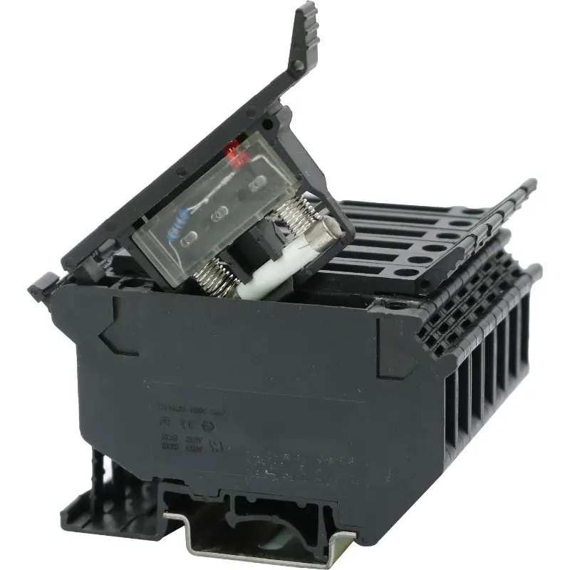
This fuse terminal can be mounted on the standard mounting rails and and can be equipped with a fuse tube (see Page 43 for details). | JWD1-4RD(R055) | 5 574 141 | 25 | |||||
Terminal with indicator lamp: (the same function as above) | Voltage (AC / DC) | Current | ||||||
Terminal with indicator lamp: (the same function as above) | 24V-48V-110V, common for AC / DC | 2-3mmA | JWD1-4RD/24V-110V AC/DC | 5 574 143 | 25 | |||
Terminal with indicator lamp: (the same function as above) | 5V-12V, common for AC / DC | 1.8-9mmA | JWD1-4RD/5V-12V AC/DC | 5 574 145 | 25 | |||
Terminal with indicator lamp: (the same function as above) | 220V-380V, common for AC / DC | 1.6-4mmA | JWD1-4RD/220V-380V AC/DC | 5 574 184 | 25 | |||
(1) Central liaison part: It is used to connect terminals with the same specification and form a liaison terminal group; each part has 10 digits (supplied with screws) that can be further divided at will. | ||||||||
(2) Connecting sheet For central connection of more than 10 digits | ||||||||
(3) Edge liaison part: Its role is the same as that of the central liaison part; with insulation on the back side; 10 digits that can be further divided at will | 2 digits: | BLS 8/2 | 8 582 182 | 100 | ||||
3 digits: | BLS 8/3 | 8 582 183 | 100 | |||||
10 digits: | BLS 8/10 | 8 582 190 | 50 | |||||
(4) Connecting strip: Used for coupling linkage of the hinge break-away arm | 4RD/LT | 8 824 101 | ||||||
(5) Tag: It can be quickly inserted in the upper grooves on both sides of the terminal as a whole for any identification. It has a total of 10 digits (to be divided at will). | White | ZP8 | 8 868 104 | 100 | ||||
Terminal dimensions | ||||||||
Thickness / width / end plate thickness | [mm] | 8.2 / 72.5 | ||||||
Height (TH 35:7.5 / TH 35:15 / G 32:15) | [mm] | 56.5/64/61.5 | ||||||
Technical data based on IEC/DIN VDE standards | ||||||||
Fuse type / dimensions & specifications | -/ [mm] | (See Page 42 for details.) | ||||||
Maximum power consumption at 23 °C based on the E DIN VDE 0611-6: 1995-05 standard | Note 1) | |||||||
Maximum cross-sectional area of conductors (rigid / flexible) that can be connected if any edge liaison part is used | [mm2] | 4/4 | ||||||
Rated impulse withstand voltage / degree of pollution | [kV]/- | 6/3 | ||||||
Over-voltage category / insulation material group | -/- | III /1 | ||||||
Connection capacity | [mm2] | |||||||
Flexible conductor with tubular bare terminal / tubular pre-insulated terminal | 0.25-4 / 0.25-4 | |||||||
Connection of multiple conductors (connecting two conductors with the same cross-sectional area) | [mm2] | |||||||
Rigid conductor / flexible conductor | [mm2] | 0.2-4/0.2-4 | ||||||
Flexible conductor with tubular bare terminal | [mm2] | 0.25-4 | ||||||
Flexible conductor with DEV-tubular pre-insulated terminal | [mm] | 0.5-2.5 | ||||||
Stripping length | 8 | |||||||
Screw type | [Nm] | M3 | ||||||
Torque | [mm] | 0.6-0.8 | ||||||
Insulation material type | PA | |||||||
Material flammability according to UL94 | V0 | |||||||
Rated working voltage / rated working current / wire gauge | UL:[V]/[A]/AWG | 800/6.3/26-10 | ||||||
Type G cartridge fuse-link with cylindrical cap ("Fuse Tube" for short) Fuse terminals with indicator lamp for special voltages can be customized upon the customer's request. | Note 1): Current subject to the fuse tube, and voltage subject to the indicator lamp | |||||||