


In industrial automation and electrical panel building, the clean routing and distribution of power define the longevity, safety, and efficiency of the entire system. A Power Distribution Block (PDB) is the critical link that takes a single high-current incoming line and splits it into multiple smaller circuits feeding PLCs, drives, or secondary terminals.
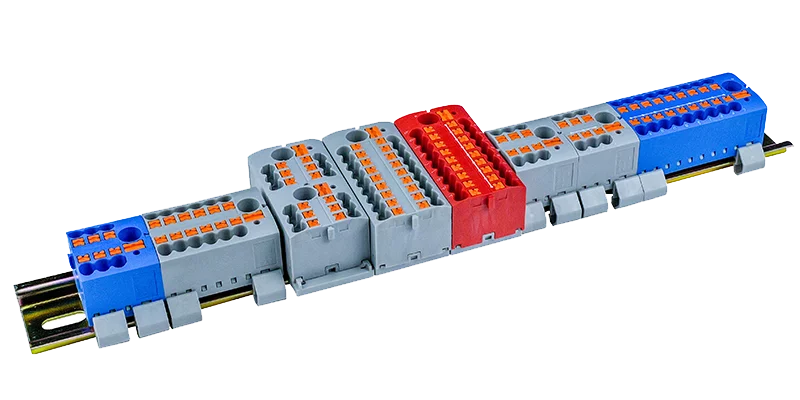
While a PDB simplifies wiring dramatically, improper installation can lead to hot spots, voltage drops, or serious safety code violations.
Whether you are working with modular interlocking blocks like the GKoncy GZ Series or traditional high-current blocks, follow this definitive step-by-step installation guide to ensure a clean, compliant, and rock-solid cabinet build.
Pre-Installation Prep: Tools & Specifications
Before cracking open the enclosure, gather the correct industrial-grade tools. Avoid guessing torque specs—precision is mandatory when handling high currents.
- Required Tools: Wire cutters/strippers, a calibrated torque screwdriver or wrench (hex or slotted depending on the terminal screw), ferrule crimping tool (if using stranded wire), and digital multimeter.
- Check the Datasheet: Verify the PDB’s maximum voltage rating (e.g., 690V/1000V), maximum continuous amperage, and specific torque values (usually measured in N·m or in-lbs) for both the line (input) and load (output) sides.
Step 1: Configure and Mount the Block
Modern PDBs offer brilliant space-saving mounting flexibility. If you are using a modular interlocking PDB, this is where you customize your phase layout.
- Assemble Modular Poles (If applicable): If you are building a 3-phase or multi-pole DC system using interlocking blocks like the GZ Series, slide the individual single-pole units together until they securely snap into place.
- Option A: 35mm DIN-Rail Mounting: Position the block over your standard DIN rail. Engage the upper mounting hook on the rail and press down firmly until the lower spring-loaded locking clip snaps into place. Pro-tip: Install mechanical end stops on both sides of the PDB to prevent lateral sliding under heavy wire bending stress.
- Option B: Direct Panel Mounting: For large-gauge wire installations where pulling forces are high, use the integrated screw holes on the base of the block to bolt the PDB directly to the steel sub-panel.
Step 2: Prepare the Incoming and Outgoing Wires
Clean wire preparation prevents stray strands from causing phase-to-phase short circuits.
- Strip the Insulation: Strip the wire jacket back to the exact depth of the PDB’s terminal channel. The raw copper/aluminum conductor should seat fully inside the collar without exposed bare metal showing outside the block body.
- Conductor Type Consideration: If you are using fine-stranded flexible cables, it is highly recommended to crimp a matching bootlace ferrule onto the wire end. This ensures uniform compression when tightened. If using solid or coarse-stranded wire, ensure the conductors are straight and free of oxidization.
Step 3: Connect and Torque the Line Side (Input)
The incoming main feed carries the full current load of your system. It must be perfectly secured.
- Insert the large main power cable into the primary input port of the distribution block. Ensure it goes all the way to the back of the lug.
- Torque to Spec: Set your torque wrench to the exact manufacturer setting. Tighten the terminal screw. Do not over-tighten, as it can strip the aluminum/brass block thread or crush the copper wires; do not under-tighten, as loose connections create high resistance, leading to thermal runaway and fire hazards.
Step 4: Route and Secure the Load Side (Outputs)
The output matrix splits the power out to individual components.
- Insert your secondary, lower-gauge wires into the respective output ports.
- Systematically tighten each output screw using the specified torque setting for that wire size (note: output torque values are often lower than input values due to smaller terminal screw sizes).
- Organize the wires cleanly into the adjacent wire ducts to minimize mechanical pulling stress on the distribution block terminals.
Step 5: Final Inspection and Safety Cover Engagement
Safety doesn’t end when the wires are tight. Final verification prevents catastrophic startup failures.
- The Pull Test: Give each wire a firm tug to ensure it is completely locked in and hasn’t clamped down onto the wire insulation by mistake.
- Clean Up Debris: Ensure no stray copper strands or metal shavings from cabinet drilling are resting inside or near the open ports.
- Close the Guard: If you are utilizing a finger-safe PDB like the GZ Series, snap the built-in hinged, transparent insulation covers closed. This ensures full IP20 touch protection, allowing future troubleshooting to happen safely even when the panel is energized.
Why System Integrators Trust GKoncy GZ Series Blocks
Installing power distribution components shouldn’t be a tedious process. The GKoncy GZ Series Power Distribution Blocks are designed by engineers, for engineers, specifically to optimize installation speed and cabinet safety.
- Mistake-Proof Assembly: The interlocking rail design ensures multi-pole blocks align perfectly on the DIN rail without loose gaps.
- Clear Visibility: Our semi-transparent safety shields allow installers to visually verify that conductors are perfectly seated without removing the protective covers.
- Industrial Ruggedness: High-torque rating capabilities paired with premium flame-retardant enclosures mean zero cracking during heavy-duty cable installation.
Simplify your next control panel build. Explore the full GZ Series technical specifications or request product samples from the GKoncy engineering team today to see how we make industrial wiring faster, safer, and more compact!